Autorouting is the greatest invention since sliced bread!

Well, not always.


During the development of this smoker controller, I did the usual steps.  I started with breadboarding sections, making them work, then gathering all the circuits together on a PCB design that I had made at OSH Park.


I am using DipTrace as my PCB software, and, like most of them, the process starts with a schematic.So, I happily drew the schematic, putting together all the parts from my breadboarding experiments.  After the schematic was done, I generated the board.  This is the point where the problem occurred.


The speed control for the fan consists of an IRF630 MOSFET driven by a PWM signal from the MCU.  I supply the fan with +12V and switch the negative return with the transistor. Since I had tested the circuit on the breadboard, I knew it worked.  All I did when I built the PCB was test it with the ‘scope to see if it was functioning.  When I finally hooked up the fan to try it, very strange things were happening.  I was getting low voltage warnings, and one of the thermocouples was signalling failure.  What happened?  This all worked when it was on the breadboard!


Autorouting is what happened.  On the breadboard, the source of the transistor was connected directly to negative through a piece of wire.On the PCB version, autorouting had taken the source, routed it through VSS on a few chips, and finally meandered back to power supply negative. I think that the PWM signal switching on and off at 20Khz was putting noise on the ground return and driving other IC’s on the board crazy.


I solved the problem by removing the speed control from the main board and making a small ‘satellite board’, connected by direct wires.  When I do the new version of the PCB, I will pay attention to this and manually route things like the speed control.  Then I will allow autorouting to take care of the simple stuff.

I’ve got a good memory – it’s just short……

So, the smoker project is progressing.  There I was,  happily adding features (like supply voltage monitoring) and then it happened – out of memory.

I’m using a Microchip PIC 16F886 microcontroller that has 8192 WORDS of memory.  In case you’re not sure what that means, a word is two bytes – so it has 16K of program memory – LOTS of memory, right?  Well, apparently not.

Now I have a dilemma – I was still going to add serial and wireless communications to it so it could notify me via text message if anything bad is happening.  That’s not going to be happening with the current board I have.  So, here’s what’s going to happen – I have stopped adding features, and will concentrate on getting the ones I have working properly.  At that point, I will work at making sure the PID process control routines are tuned perfectly, and I will have a complete, working, charcoal smoker temperature controller,

Next winter, I will have a new version of the board that uses a PIC 18F2550 microcontroller – one that has 32K words of memory – more than enough (yeah, right, I said that about the 16F886!),  Below is a screen shot of the new design – all through hole except for the resistors, they are SMD on the underside.  I think I will make this board all SMD when I get around to making it.

Image

Oh yeah, the voltage monitoring – when I designed the V1 board, I included a voltage divider that goes to another ADC channel on the microcontroller.  A little bit of programming, and I am able to sample and display the supply voltage within 100 millivolts – more than accurate enough.  The user can press a button in auto mode that will display the voltage for five seconds, and the supply voltage is being checked twice a second during error checking.  If the voltage drops to 10.5Vdc or lower, the fan and solenoid are powered down and the unit starts beeping an error.  On the display, the user is prompted to turn the unit off and change the power supply.  When it powers back up, a status bit is read in the on-board EEPROM that bypasses the title screen and setup for that power-up only.  It goes directly back to Manual Mode so the smoker doesn’t get out of control.

The reason for this is that smokers sometimes get used where there is no Hydro – no power to run a power supply.  A battery is the only option, and some of those BIG pork shoulders take many hours to cook.  Just a way of ensuring that everything is working well.

There are still a couple of glitches to clear up and I’m ready for BBQ season!  Now if only the 6ft of snow in my yard would melt!

Now that it works, what next?

Ok, so my test bed worked on a basic level.  All my testing was with the bare board, but now I had a nice circuit board to make it pretty.  I never even hooked up the switches during testing, just touched the various wires together.

I should explain my idea for the controls of this thing.  I wanted it simple, so I decided that I would have only a power switch and three push buttons under the screen – one under thye left side, one under the right, and one in the middle.  The bottom line of the LCD would tell you what the function of the button is at this particular time.  The functions of each button change with each screen.

The only problem was the two line by 16 character LCD – not enough room for what I needed.  It worked, but it could look nicer.  So I swapped it for a four line by 20 character backlit LCD.  More room and visible at night for those long overnight cooks.  I had to make quite a few changes in the software to run the new screen, but it wasn’t too bad.  The new screen gives me lots more room to display things, while at the same time, still displaying the button functions on the bottom line.

It was about this time that I added an ‘Easter Egg’ to the program.  Well, not really an Easter Egg, but a hidden function. Before this, I wrote a small program that displayed the sampled ADC value from a thermocouple.  The I put the thermocouple in a pot of water on the stove and heated it to boiling.  At various times, I checked the actual temperature with a known-good thermometer and recorded that value and the ADC value at that point.  After I got it to boiling, I had a ‘compensation number’ to use in the program to convert the raw ADC value to degrees F.

The only problem was, it was hard coded.  So I decided to write a hidden routine to calibrate the thermocouples.  Its entered by holding down the left button on power up, and continuing to hold it through the title screen, and for a further two seconds after the screen blanks.  At that point, you are told to release the button and then you can make a choice as to which thermocouple you want to calibrate.

In the calibration routine, you are shown the current adjustment value and the current temperature in degrees F.  All you do is put the thermocouple in a known-temperature pot of water (boiling works good) and use the left and right buttons to adjust the displayed temperature to 212F.  When you press the right button (enter) the value is written to the on-board EEPROM and is read at startup.

Since I already had ONE easter egg in it, the Hackaday Fubarino Contest (http://hackaday.com/2013/12/03/new-contest-win-one-of-20-microchip-fubarino-boards/) was a natural to add another.

Not that this is much of an Easter Egg, but it exists.  On startup, if you follow the same procedure as the calibration routine, only this time holding the middle AND right buttons, the Easter Egg is revealed for 5 seconds.  Below is a video of the startup and the Hackaday Easter Egg.  Remember, I’m still developing stuff and its not even in a box – heck, there are no buttons yet, just wires to touch together.

Here’s a video of the startup with the middle and right buttons operated:

After this, the next steps are to put it in a box, add the serial logging function, put it in a box, add monitoring of the input voltage with an ADC port and a voltage divider I put on the board, put it in a box, add WiFi functions, and put it in a box.

You might have noticed that this REALLY needs a project box!  I getting tired of staring at a bare board, but its SO much easier to work on the way it is now.

First steps to BBQ bliss (at least for me)

So I had to learn a few things……..

First I started with ProtoBoard and added a microcontroller (PIC 16F886) and a two line by 16 character LCD.

I wrote a program that displayed text on the LCD – step one was complete.  I then added an IRF630 MOSFET as a speed controller and learned how to control the speed of a fan –  step two.

The next learning step was a little tougher – I had never worked with any analog to digital sampling before.  Thermocouples work by generating a voltage in relation to the temperature of the junction.  The only problem is that its only 44 microvolts per degree celcius (for the K-type thermocouples I was using). This is a very small voltage to sample, so an OP-Amp is needed to boost the level to something more easily measurable.  In addition, the junction that you measure the voltage at causes issues too – its another junction.

The answer?  The Analog Devices AD595 – a ready-made thermocouple interface that outputs 10 millivolts per degree celcius, compensates for the measurement junction, and even has an alarm output that signals if a thermocouple fails!  Perfect!
Using the AD595’s made my first analog-to-digital attempts easy.

I spent a  couple of weeks writing software to read the thermocouple inside the smoker and control to speed of a 12VDC fan to reulate the temperature.  I also added alarm points and monitoring of the meat temperature through another thermocouple.

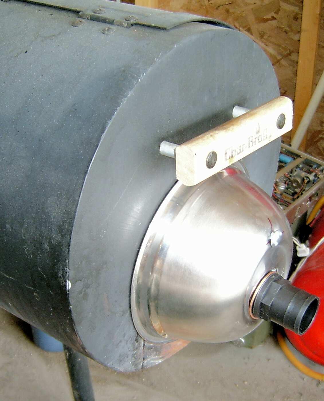
Now that I had a way to control it – I needed a fan.  I mounted a computer fan in the side of a Rubbermaid container, put a plate to seal the fan in and mounted a 1 1/4″ hose barb to let the air out.  I unbolted the damper from my smoker, and mounted a stainless steel bowl with a hose barb.  See the below picture for an idea of what I mean.

In the picture, you might notice that the hose barb is plastic – that REALLY didn’t work out so well!  It has since been changed to a metal barb insulated with high temperature rubber tape – works great with plastic hose as the connection between fan and manifold.
I did a bunch of experimenting with the settings of the program, and got everything tuned up so that it keeps the temperature within 5 degrees F or so – more than close enough for my purposes.
Here’s a picture of the test-bed board I ended up with (some parts have been removed and are on the new version):
Image
After that, I decided that I needed it to be a little “classier”.  So I bought a license for one of the entry-level versions of DipTrace and designed a PCB that I had made by OSHPark.  Here’s that board:
pcb
I have since built up the board and it works great!  Next I’ll document the changes I made once I had the couple of mistakes I made on the PCB fixed.  How is it that I spent HOUR AFTER HOUR checking everything on the design, and it still had two mistakes?  They were both easily fixed in a couple of minutes, but still……….

BBQ and electronics – a match made in heaven?

I’m just going to come out and say it – I LOVE BBQ!

To me, there;s nothing better than pulling that gorgeous pork shoulder from the smoker, shredding it, and creating FABULOUS pulled pork sandwiches with the result.  I have experimented for years and come up with some winners – and a lot of losers – along the way.  The losers are all part of the learning process.

I’ve used a couple of different smokers, and the most difficult thing about it is keeping the temperature where you want it.  It sometimes requires constant attention.

Last winter, I was wandering around the internet and came upon a link from Alton Brown’s blog (he my culinary hero) to the Pitmaster IQ temperature controller. In the Good Eats episode “Right On Q”, Mr. Brown used the temperature controller to keep his smoker at the perfect temperature to cook BBQ.

Here’s the episode on YouTube.  He starts talking about the temperature controller at around 36:48.

My thought on seeing this was: “I can make that!”  I’ve been making microcontroller projects as a hobby for years.

I did some more research (read: Google Searches) and found that there are DOZENS of these things, ranging in price from $150 to $500 units with LCD graphing displays, bluetooth and wireless control, and more!

After looking at features, I decided on the following requirements for my controller:

1) Capable of being powered from a power supply or battery.

2) LCD screen

3) Simple controls (many of the ones out there have lots of buttons and switches)

4) PID process control to maintain the temperature

5) PWM control of fan speed

6) Meat probe to monitor meat temperature

7) Serial (RS-232) port to be used for logging to PC, or communications with modules such as

Bluetooth or Wireless.

I then sat down and started to figure out what I needed to do to accomplish this.  I had never used an LCD display on a project before – so that was first.  Second was reading a thermocouple using an ADC port (never done that either).  Third was PWM control of a motor – I had controlled the brightness of LED’s before, but never a motor. I had also never created a microcontroller serial port before,

My path was set: next time I’ll talk about the experiments that led me to where I am now.